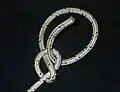
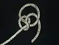
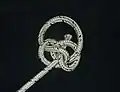
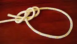
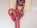
Note(s): Named for Philip Hinckaert, maître d’hôtel to Philip the Handsome in the late 15th century.
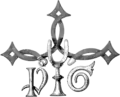
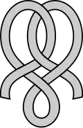
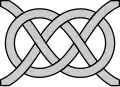
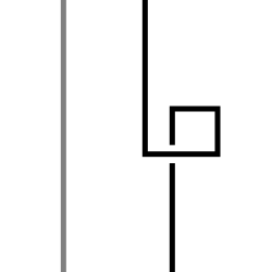
The Hinckaert knot, a type of decorative unknot, is a heraldic knot used primarily in Dutch heraldry. It is most notable for its appearance on the Hinckaert family heraldic badge, where a semi-angular form is used as canting arms, a common practice with heraldic badges.
The name “Hinckaert” is delineated as a derivation of hincken, “to limp”, in the badge. Hence the center crutch, and the buckle on the knot, implying that it is a strap used to attach the crutch to the leg.[1] The dexter “P” and sinister “G” are traditionally translated as standing for Philip (Hinckaert), with whom the knot originated, and his wife, née Gasparine.[1]
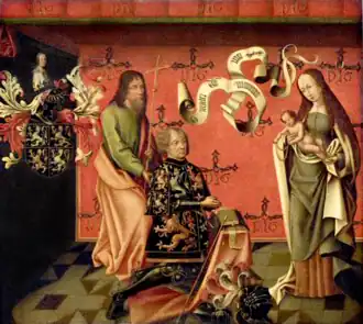
A portrait of Philip Hinckaert (kneeling). In the background the wall is diapered in the Hinckaert knot.
References
12Archaeologia: or, Miscellaneous Tracts Relating to Antiquity. Harvard University: Society of Antiquaries of London. 1887. pp.73–74.
This article is adapted from “Hinckaert knot” on Wikipedia, written by its contributors, and used under CC BY-SA 4.0. Text on this page is available under the same licence. Source snapshot: Wikipedia via Kiwix, 2026-07-20.
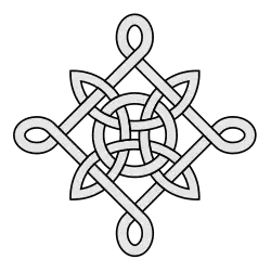
A heraldic knot (referred to in heraldry as simply a knot) is a knot or design incorporating a knot used in European heraldry.[1] While a given knot can be used on more than one family’s achievement of arms, the family on whose coat the knot originated usually gives its name to the said knot (the exception being the Tristram knot). These knots can be used to charge shields and crests, but can also be used in badges or as standalone symbols of the families for whom they are named (like Scottish plaids). The simplest of these patterns, the Bowen knot, is often referred to as the heraldic knot in symbolism and art outside of heraldry.
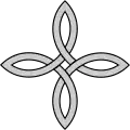
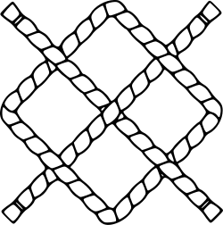
Drawing of a heraldic knot consisting only of right angles, such that it looks like a square turned 45° on its side (so the corners point to the cardinal directions) with a cross (turned to resemble the letter ‘X’) going through the square which bisects each of the square’s four sides.
This article is adapted from “Heraldic knot” on Wikipedia, written by its contributors, and used under CC BY-SA 4.0. Text on this page is available under the same licence. Source snapshot: Wikipedia via Kiwix, 2026-07-20.
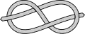
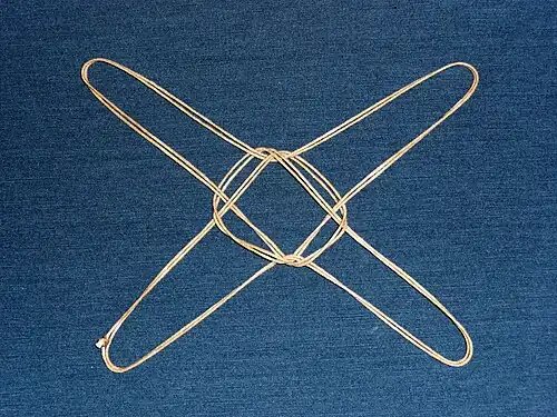
Heraklas’ sling XIII, the plinthios brokhos is produced in the same manner as a string figure. This example is formed in a doubled cord for better visibility.The diplous karkhesios brokhos or the modern bottle slingThe epankylotos brokhos or the modern Tom fool’s knot
Heraklas (Ancient Greek: Ἡρακλᾶς) was a Greek physician of the 1st century AD whose descriptions of surgeons’ knots and slings are preserved in book 48 of Oribasius’ Medical Collections (Ἰατρικαὶ Συναγωγαί, Iatrikai Synagogai) under the title From Heraklas.[1]
Describing them in detail, Heraklas discussed 16 different knots and slings,[1] including the earliest known written account of a string figure.[2] Accompanying illustrations of the knots were added later by Renaissance copyists, but modern analysis of the writings by knot experts has shown many of these early drawings to contain significant errors or misinterpretations.[3]
The knots identified
The current understanding of Heraklas’ knots results primarily from analysis and identification by Hjalmar Öhrvall, Lawrence G. Miller, and Cyrus L. Day, although slightly differing interpretations and refinements continue to be made.[1] The table below shows the knots believed to have been described by Heraklas.
123Hage, J. Joris (April 2008), “Heraklas on Knots: Sixteen Surgical Nooses and Knots from the First Century A.D.”, World Journal of Surgery, vol.32, no.4, pp.648–655, doi:10.1007/s00268-007-9359-x, PMID18224483
↑Miller, Lawrence G. (1945), “The Earliest (?) Description of a String Figure”, American Anthropologist, New Series, 47 (3): 461–462, doi:10.1525/aa.1945.47.3.02a00190
↑Day, Cyrus L. (1967), Quipus and Witches’ Knots, Lawrence: University of Kansas Press, pp.86–89, 101–151
↑Although topologically identical, it is used in a different manner than “VII, Hercules knot”. Specifically the bound object (e.g. a limb) is placed in the center of the reef knot.
↑See Caroline Furness Jayne’s String Figures and How to Make Them (1906), p. 383, Roth Plate X, 1. and discussion p. 162. N. B. Miller (1945) correctly points out the difference of a single crossing in Jayne’s fig. 359, p 161.
↑Although topologically identical, it is used in a different manner than “IX, single jug-sling noose”.
↑Although topologically identical, it is used in a different manner than “II, nautical noose”.
This article is adapted from “Heraklas” on Wikipedia, written by its contributors, and used under CC BY-SA 4.0. Text on this page is available under the same licence. Source snapshot: Wikipedia via Kiwix, 2026-07-20.
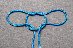
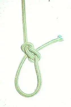
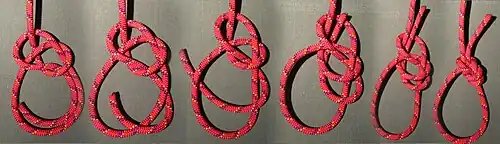
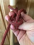
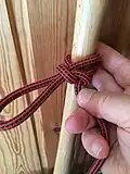
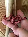
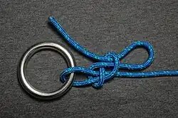
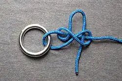
A zeppelin eye knot, is a secure, jam resistant fixed size loop knot based on the zeppelin bend. It is one of the few eye knots suitable for bungee. It is also special in its ease of untying.
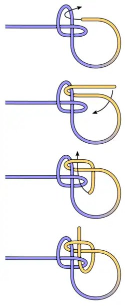
Tying the Zeppelin loop
Tying
Virtually all bends (i.e. end-to-end joining knots) have a corresponding ‘eye knot’. For example, the Sheet bend (ABoK #1431) has a corresponding eye knot which is none other than the common (#1010) Bowline. The Zeppelin bend is formed from 2 superposed loops of opposite chirality.
There are two versions of the zeppelin eye knot depending on how it is tied.
The first version where the end seems to be vertical to the main part, and one of the loop sides seems to be the continuation of the main part, while the other loop side seems to continue as the working end out of the loop knot. This version is tied using the clover method, starting with an overhand knot, then letting the working end pass in the following order through
first the eye of the clover (overhand knot) on the main part side along with the main part (thus forming the loop)
then the loop itself opposite the direction of the main part
and last the other eye of the clover knot in the opposite direction of the exiting working end (loop side)
The other version where the end seems to be the continuation of the main part, and both ends of the loop seems to be vertical to the main part. This version is tied using the clover method, starting with an underhand knot, then letting the working end pass in the following order through
– the same eye to form a simple noose thus forming the loop
– around the edge of the underhand knot, and through the loop of the noose
– around and through the knot along with the main part ( thus passing simultaneously through all 3 of the original underhand knot, the noose and the last round of itself).
Tying a jamming false Zeppelin loop using the noose method: One starts with an underhand knot
The working end is brought back in through the same eye to form a simple noose thus forming the loop
The working end is led around the edge of the underhand knot, and through the loop of the noose
The working end is led around the knot to reenter and cross it alongside the main part ( thus passing through all 3 loops of underhand knot, noose and its own).
This article is adapted from “Zeppelin loop” on Wikipedia, written by its contributors, and used under CC BY-SA 4.0. Text on this page is available under the same licence. Source snapshot: Wikipedia via Kiwix, 2026-07-20.
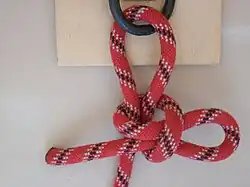
A Yosemite bowline is a loop knot often perceived as having better security[1] than a bowline. If the knot is not dressed correctly, it can potentially collapse into a noose,[1][2][3][4] however testing reveals this alternative configuration to be strong and safe as a climbing tie-in.[5]
A Yosemite bowline is made from a bowline with the free end wrapped around one leg of the loop and tucked back through the knot, a final round turn and reeve commonly known as a “Yosemite finish.” The knot’s security is enhanced by preventing the bowline capsizing to form a highly dangerous slip knot. Additional safety is achieved by tying with a tail (see below). When finished, the working end forms a figure eight.
Because of the danger of incorrectly dressing the Yosemite bowline and capsizing it even before it is set, it may be safer and less error-prone to use a standard or double bowline with a backup stopper knot added to the tail, such as a double overhand knot tied around the loop.[3][4]
The Yosemite finish can be applied to other bowline variants, such as the double bowline.
While the knot’s versatility suggests it as a convenient tie-in for attaching a climbing rope to a climber’s harness, the figure-of-eight follow through is the most common choice because it is more widely known and more easily checked.[6]The Mountaineering Handbook is one of the few texts that suggest that the Yosemite bowline is better for this purpose. Suggested benefits of the bowline include being easier to untie after loading or when wet and frozen, and being possible to tie-in with only one hand.[7] Testing found it a strong knot for the purpose.[8]
It is recommended that any knot which is used to attach a rope to a safety harness is always finished with a stopper knot. A stopper knot, while serving to keep the loose end tidy, will only help to prevent failure of the primary knot, and does not act as a secondary safety knot by itself. It is sometimes said that if enough of a tail is left to tie a stopper knot, the stopper becomes unnecessary. The tail should be a minimum of 10cm but depends on the thickness of the rope.[9]
12Gommers, Mark (18 November 2017). “An analysis of the structure of Bowlines”. Professional Association of Climbing Instructors. Retrieved 2018-10-06. ‘Yosemite’ variation of the Bowline is an attempt to make the standard #1010 structure more secure. … care must be taken not to draw the tail up before setting the nipping loop or it may become displaced and compromise the knot.
↑Prohaska, Heinz (April 1988). “A Safer Bowline for Climbers and Cavers”. Nylon Highway. 26: 4–5. Archived from the original on October 6, 2018. Retrieved October 6, 2018. This idea looks really good, but has a serious and unexpected disadvantage. The parallel parts of the rope in the knot can change their places before it is tightened, and if this happens, the finished knot can work loose and/or turn into a noose—much easier than a regular bowline.{{cite journal}}: CS1 maint: bot: original URL status unknown (link)
12Grogono, Alan W.; Grogono, David E. “Bowline Knot – How to tie a Bowline Knot – Climbing Knots”. Animated Knots. Tighten the Bowline first and then tighten the Yosemite Tie-Off. Failure to do so can result in a slip knot. … A Safety Knot is essential, e.g., a Double Overhand (Strangle Knot) can be tied around either the adjoining loop (left)
↑Gaines, Bob; Martin, Jason D. (2014-05-20). Rock Climbing: The AMGA Single Pitch Manual. Rowman & Littlefield. ISBN9781493009626. the uniform nature of the knot enables quick inspection and supervision.
This article is adapted from “Yosemite bowline” on Wikipedia, written by its contributors, and used under CC BY-SA 4.0. Text on this page is available under the same licence. Source snapshot: Wikipedia via Kiwix, 2026-07-20.
In knot theory, there are several competing notions of the quantity writhe, or . In one sense, it is purely a property of an oriented link diagram and assumes integer values. In another sense, it is a quantity that describes the amount of “coiling” of a mathematical knot (or any closed simple curve) in three-dimensional space and assumes real numbers as values. In both cases, writhe is a geometric quantity, meaning that while deforming a curve (or diagram) in such a way that does not change its topology, one may still change its writhe.[1]
Writhe of link diagrams
In knot theory, the writhe is a property of an oriented link diagram. The writhe is the total number of positive crossings minus the total number of negative crossings.
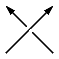
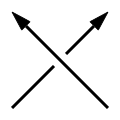
A direction is assigned to the link at a point in each component and this direction is followed all the way around each component. For each crossing one comes across while traveling in this direction, if the strand underneath goes from right to left, the crossing is positive; if the lower strand goes from left to right, the crossing is negative. One way of remembering this is to use a variation of the right-hand rule.
Positive crossing
Negative crossing
For a knot diagram, using the right-hand rule with either orientation gives the same result, so the writhe is well-defined on unoriented knot diagrams.
The writhe of a knot is unaffected by two of the three Reidemeister moves: moves of Type II and Type III do not affect the writhe. Reidemeister move Type I, however, increases or decreases the writhe by 1. This implies that the writhe of a knot is not an isotopy invariant of the knot itself — only the diagram. By a series of Type I moves one can set the writhe of a diagram for a given knot to be any integer at all.
Writhe of a closed curve
Writhe is also a property of a knot represented as a curve in three-dimensional space. Strictly speaking, a knot is such a curve, defined mathematically as an embedding of a circle in three-dimensional Euclidean space, . By viewing the curve from different vantage points, one can obtain different projections and draw the corresponding knot diagrams. Its writhe (in the space curve sense) is equal to the average of the integral writhe values obtained from the projections from all vantage points.[2] Hence, writhe in this situation can take on any real number as a possible value.[1]
In a paper from 1961,[3] Gheorghe Călugăreanu proved the following theorem: take a ribbon in , let be the linking number of its border components, and let be its total twist. Then the difference depends only on the core curve of the ribbon,[2] and
.
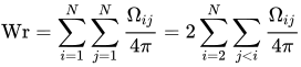
In a paper from 1959,[4] Călugăreanu also showed how to calculate the writhe Wr with an integral. Let be a smooth, simple, closed curve and let and be points on . Then the writhe is equal to the Gauss integral
.
Numerically approximating the Gauss integral for writhe of a curve in space
Since writhe for a curve in space is defined as a double integral, we can approximate its value numerically by first representing our curve as a finite chain of line segments. A procedure that was first derived by Michael Levitt[5] for the description of protein folding and later used for supercoiled DNA by Konstantin Klenin and Jörg Langowski[6] is to compute
,
where is the exact evaluation of the double integral over line segments and ; note that and .[6]
To evaluate for given segments numbered and , number the endpoints of the two segments 1, 2, 3, and 4. Let be the vector that begins at endpoint and ends at endpoint . Define the following quantities:[6]
Finally, we compensate for the possible sign difference and divide by to obtain[6]
In addition, other methods to calculate writhe can be fully described mathematically and algorithmically, some of them outperform method above (which has quadratic computational complexity, by having linear complexity).[6]
Applications in DNA topology
DNA will coil when twisted, just like a rubber hose or a rope will, and that is why biomathematicians use the quantity of writhe to describe the amount a piece of DNA is deformed as a result of this torsional stress. In general, this phenomenon of forming coils due to writhe is referred to as DNA supercoiling and is quite commonplace, and in fact in most organisms DNA is negatively supercoiled.[1]
Any elastic rod, not just DNA, relieves torsional stress by coiling, an action which simultaneously untwists and bends the rod. F. Brock Fuller shows mathematically[7] how the “elastic energy due to local twisting of the rod may be reduced if the central curve of the rod forms coils that increase its writhing number”.
↑Levitt, Michael (1986). “Protein Folding by Restrained Energy Minimization and Molecular Dynamics”. Journal of Molecular Biology. 170 (3): 723–764. CiteSeerX10.1.1.26.3656. doi:10.1016/s0022-2836(83)80129-6. PMID6195346.
Adams, Colin (2004), The Knot Book: An Elementary Introduction to the Mathematical Theory of Knots, American Mathematical Society, ISBN978-0-8218-3678-1
This article is adapted from “Writhe” on Wikipedia, written by its contributors, and used under CC BY-SA 4.0. Text on this page is available under the same licence. Source snapshot: Wikipedia via Kiwix, 2026-07-20.
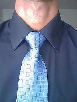
The Windsor knot, sometimes referred to as a full Windsor (or misleadingly as a double Windsor) to distinguish it from the half-Windsor, is a knot used to tie a necktie. As with other common necktie knots, the Windsor knot is triangular, and the wide end of the tie drapes in front of the narrow end. The Windsor is a wider knot than most common knots, and while not truly symmetric is more balanced than the common four-in-hand knot. The Windsor’s width makes it especially suited to be used with a spread or cutaway collar.
History and adoption
The knot is named after the Duke of Windsor. He is sometimes credited with its invention[1] alongside his London shirtmaker.[2] It is however the case that the Duke achieved the wide knot that was his signature by wearing ties of thicker cloth that produced a wider knot from the conventional four-in-hand, and hence the Windsor knot was likely invented to emulate the Duke’s wide knots using ties of normal thickness.[3]
It is also the only accepted knot for the SD tie of the RAAF and AAFC in Australia.[4]
The Windsor is notably favored by many United States politicians, such as Donald Trump.[5]
This article is adapted from “Windsor knot” on Wikipedia, written by its contributors, and used under CC BY-SA 4.0. Text on this page is available under the same licence. Source snapshot: Wikipedia via Kiwix, 2026-07-20.
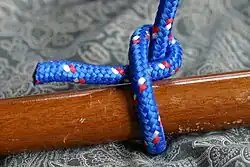
The halter hitch is a type of knot used to connect a rope to an object. As the name implies, an animal’s lead rope, attached to its halter, may be tied to a post or hitching rail with this knot. The benefit of the halter hitch is that it can be easily released by pulling on one end of the rope, even if it is under tension. Some sources show the knot being finished with the free end running through the slipped loop to prevent it from working loose or being untied by a clever animal, still allowing easy but not instant untying.[1][2]
Tying
Halter hitch 1: Place rope behind, through or around anchor object. Form a loop in the working part of the rope.
Halter hitch 2: Pull a bight of the working part behind the standing part and then through the loop formed in first step.
The halter hitch can be derived from the Noose knot by turning the working end into a bight.
Difference from similar hitches with the same purpose
The halter hitch is topologically the same knot as the Falconer’s knot, i. e. a slipped overhand knot around the main part.[3] The falconer has to tie the same knot one handed, throwing the end around the anchor object (the perch), gripping it with a scissoring fingers act, pulling the bight from opposite side of the main part using the back of the thumb.
Falconer’s knot 1: Pinching fingers from below, hooking thumb from above
Falconer’s knot 2: Hand rotated counterclockwise in a “GO AWAY” sign from below
Falconer’s knot 3: End bight scissored between fingers to thumb loop
Falconer’s knot 4: End bight slipped through loop around thumb
Falconer’s knot 5: Tightened by pulling main part, pushing the knot
Falconer’s knot 6: Locked with free end through slip
The halter hitch is similar to other slipped hitches that wrap the main part with small differences:
The Siberian hitch is one where the bight for the slip is twisted one more time i.e. a slipped Figure-eight knot around the main part. Stronger, traditionally used to tie a horse or reindeer by evenks in Siberia, tied with a method suitable for tying while wearing a glove.
The Slippery hitch and Buntline hitch are essentially a slipped Clove hitch around the main part. Slippery hitch has the slip placed under the last turn away from the main part, while Buntline hitch has the slip placed under the last turn towards the main part. Easy to tie, secure, easy to untie, Slippery hitch is used several in a row on square-rigged ships for securing the gaskets that bind stowed sails to the yards on top, while Buntline hitch, stronger but more difficult to untie, is used slipped to secure the bottom of open sail.
The half hitch with slip is one with no extra bight, no extra turn, just a slip inside the half hitch, much weaker than all of the above hitches.
This article is adapted from “Halter hitch” on Wikipedia, written by its contributors, and used under CC BY-SA 4.0. Text on this page is available under the same licence. Source snapshot: Wikipedia via Kiwix, 2026-07-20.
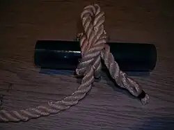
The half hitch is a simple hitch knot, where the working end of a line is brought over and under the standing part. Insecure on its own, it is a valuable component of a wide variety of useful and reliable hitches, bends, and knots.
The half hitch is tied with one end of a rope which is passed around an object and secured to its own standing part with a single hitch.
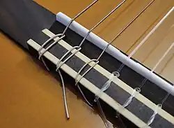
Securing an additional single hitch to the rope’s standing part produces the related knot two half-hitches.[1]:283Alternatively, a half hitch may be made secure on its own by placing the final crossing opposite to the turn around the working end. This locks the end in place, and holds fast as long as the hitch is loaded by a steady pull.[1]:290 A half hitch in this configuration is sometimes used to tie strings to the bridge of a classical guitar.
An instance of secure half-hitches, seen in the thicker strings on the left.
Another instance where a half hitch stands on its own without additional embellishment is when added to a timber hitch to help stabilize a load in the direction of pull. A timber hitch is tied on the far end of the load to bind it securely and a half hitch made at the forward end to serve as a guide for the rope. In this instance, the half hitch combined with a timber hitch is known as a killick hitch or kelleg hitch.[2]
The knot is attractive to the eye and so is used decoratively for French whipping which is also known as half hitch whipping.[3]
This article is adapted from “Half hitch” on Wikipedia, written by its contributors, and used under CC BY-SA 4.0. Text on this page is available under the same licence. Source snapshot: Wikipedia via Kiwix, 2026-07-20.
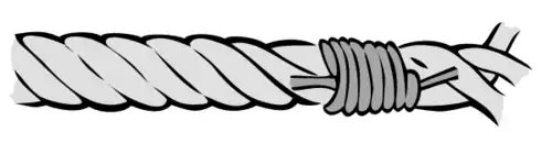
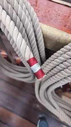
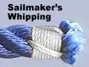
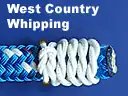
A whipping knot or whipping is a binding of marline twine or whipcord around the end of a rope to prevent its natural tendency to fray.
Some whippings are finished cleanly, as by drawing the bitter end of the cordage beneath the whipping itself. Others are tied off or have the end(s) of the twine sewn through the rope. According to The Ashley Book of Knots, “The purpose of a whipping is to prevent the end of a rope from fraying … A whipping should be, in width, about equal to the diameter of the rope on which it is put … [Two sailmaker’s whippings], a short distance apart, are put in the ends of every reef point, where the constant ‘whipping’ against the sail makes the wear excessive; this is said to be the source of the name whipping.”[1] The other type of stopping knot is a seizing knot.
A common whipping knot on the BAP Unión using the colors of the flag of Peru
Whipping is suitable for synthetic and natural stranded and braided lines, including 3-strand rope, 4-strand cable and 8-strand multiplait, as well as concentric and braided constructions.
Tying
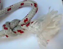
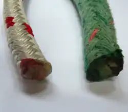
Unsecured end of double braid rope
Multiple turns of twine (sometimes called small stuff for smaller lines) or heavier whipcord (for large diameter cables and ropes) are tightly wrapped around a rope’s cut end to prevent its fibers from unlaying.
Usually one end of the whipping cord is looped along the rope to be whipped, and the remaining cord wound tightly over the loop. Finally the loose end of the wound whipping is passed through the loop so that both ends may be drawn securely inside the winding.[2]
Whippings may also be applied by hand or using a palm and needle, and either simply tied off or made neat and permanent by reeving the twine’s cut ends into or behind the whipping, sewing them to adjacent strands, or through the rope itself.
In applications where a lot of flexing is expected, the whipping may be impregnated with dilute spar varnish or superglue.
French whipping is merely a series of half hitches. Start with a running eye and finish up with the end tucked back under the last few hitches. The ridge of the hitches should follow the lay of the rope.
French whipping is a whipping knot that consists of a series of half hitches. It is used to stop unraveling of rope ends as well as to provide a grip over railings.[3]
Portuguese whipping is the quickest of all to apply; the ends are merely reef knotted together. It is given by Esparteiro in his Dicionario de Marinharia (Lisboa, 1936).
The Portuguese whipping is a type of whipping knot. To make it you take the small diameter string and lay one end against the rope. Wrap backwards up the rope until you have both ends side by side, finish by tying a reef knot. This is the quickest of the seizings, but is not as secure as some.[5]
Alternatives
Constrictor knot
A constrictor knot can be used temporarily to hold the fibres of a cut line until a final whipping can be applied.
Tape
Several turns of self-adhesive plastic tape may form a temporary or emergency substitute for whipping.
Fusion
Rope ends heat sealed with electric knife
The ends of some man-made fibers such as Dacron, Nylon, polyethylene, polyester, and polypropylene (but not aramid fibers) may be melted to fuse their fibers to prevent fraying. However, the rope and knotting expert Geoffrey Budworth warns against this practice for boat operators thus:[6]
Sealing rope ends this way is lazy and dangerous. A tugboat operator once sliced the palm of his hand open down to the sinews after the hardened (and obviously sharp) end of a rope that had been heat-sealed pulled through his grasp. There is no substitute for a properly made whipping.
Among the methods of fusing are using an electrically heated rope cutter, heating the blade of a knife, or melting cut ends in a flame. The cool (transparent) part of a butane lighter flame works best.
It is helpful to wrap the end of a line to be fused with several turns of plastic tape first. The finished end will be neater and narrower if a cut is made through the tape.
Back splice
Back splicing uses a stranded rope’s own fibres to prevent fraying. A back splice adds extra thickness to the rope end, preventing it from running through blocks and sheaves. It can also be of benefit when a user needs to feel the end of the rope, as on a bucket lanyard.[7]
Liquid
Liquid whipping is a semi-permanent rubbery coating applied by dipping the cut end of a line into a container of the product. When the coating sets it is flexible but solid enough to keep the rope together. Liquid whipping can be used on both natural and synthetic fibers.
Aglet
An aglet is a permanent ending applied mechanically to bind the end of the rope. A typical example is the plastic aglet at the end of a shoelace. Metal aglets may be crimped onto ropes or cables. Aglets may also be made by melting a softer metal to cap the end of the cable.
This article is adapted from “Whipping knot” on Wikipedia, written by its contributors, and used under CC BY-SA 4.0. Text on this page is available under the same licence. Source snapshot: Wikipedia via Kiwix, 2026-07-20.