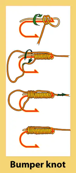
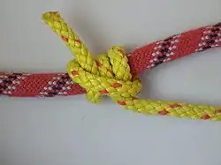
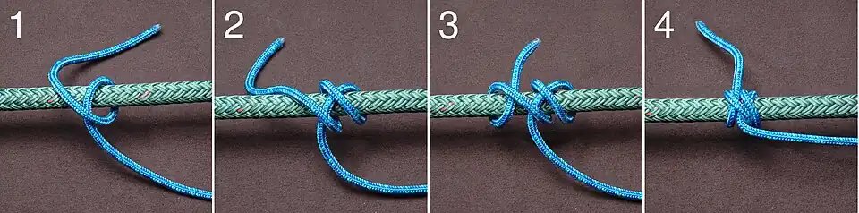
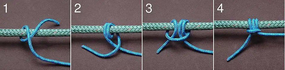
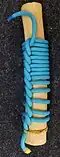
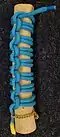
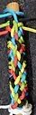
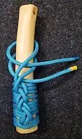
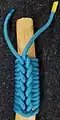
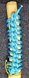
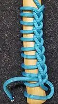
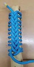
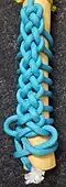
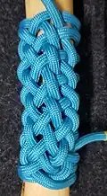
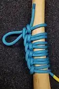
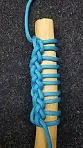
In fishing, a bumper knot (also known as a bait loop or egg loop) can be used to secure soft or loose bait, including clusters of eggs, to a hook.
Instructions
The first suggestion for tying the bumper knot is to always keep the loops tight. If the loops become loose at all the knot will not work. The initial string used for the lead usually consumes about 8 inches when tying. To start tying the knot, hold the bend of the hook, and start feeding one end of the line through the eye of the hook. Do this until it is possible to grasp it with the same fingers holding the hook. After that, start to wrap the line around the shank of the hook in a clockwise direction. It is known that the first loop is also the toughest to make. Altogether, about 18-20 loops will be adequate. It needs to be tight and there needs to be a lot of pressure on the line. Then place the opposite end of the leader in a parallel direction to the shank of the hook and put it through the eye. All this needs to be done so that the previous loops do not come undone. Wrap over the line that is put through the eye, and make these wraps clockwise. On this set, it is recommended to only wrap with medium pressure. For about four or five wraps, continue to work with this process and make sure that they do not overlap. Then grasp all of the wraps on the hook to hold them tightly. Then pull the line hanging out of the eye and pull it through the wraps. The final step is to make everything snug and in place.[1]
References
↑“Egg Loop Knot”. Piscatorial Pursuits. Retrieved 2 January 2013.
This article is adapted from “Bumper knot” on Wikipedia, written by its contributors, and used under CC BY-SA 4.0. Text on this page is available under the same licence. Source snapshot: Wikipedia via Kiwix, 2026-07-20.
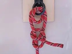
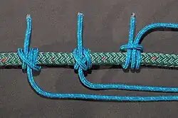
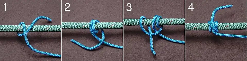
The round turn and two half hitches is a hitch used to secure the end of a rope to a fixed object. The name refers to the components used to form the knot: a round turn wraps the rope around the object (completely encircling it) and the two half hitches secure the end around the standing part. Variations of this hitch can be made with differing numbers of turns and half-hitches; an example is illustrated below. With additional turns, it becomes a pipe hitch.
The Round Turn and Two Half Hitches is named by Steel in 1794. If a spar is small, a round turn is preferable to a single turn. It makes a stronger knot and dissipates the wear.
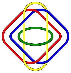
In knot theory, a branch of topology, a Brunnian link is a nontrivial link that becomes a set of trivial unlinked circles if any one component is removed. In other words, cutting any loop frees all the other loops (so that no two loops can be directly linked).
The name Brunnian is after Hermann Brunn. Brunn’s 1892 article Über Verkettung included examples of such links.
Examples
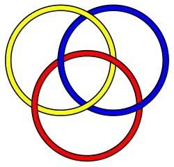
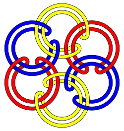
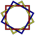
The Borromean rings are the simplest Brunnian link.Six-component “rubberband” Brunnian link. The same construction leads to Brunnian links with arbitrary numbers of components.
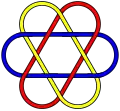
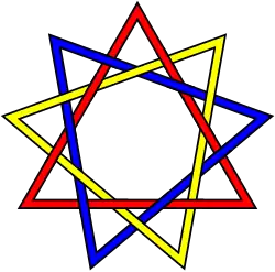
The best-known and simplest possible Brunnian link is the Borromean rings, a link of three unknots. However for every number three or above, there are an infinite number of links with the Brunnian property containing that number of loops. Here are some relatively simple three-component Brunnian links which are not the same as the Borromean rings:
12-crossing link.
18-crossing link.
24-crossing link.
The simplest Brunnian link other than the 6-crossing Borromean rings is presumably the 10-crossing L10a140 link.[1]
An example of an n-component Brunnian link is given by the “rubberband” Brunnian Links, where each component is looped around the next as aba−1b−1, with the last looping around the first, forming a circle.[2]
In 2020, new and much more complicated Brunnian links were discovered in [3] using highly flexible geometric-topology methods. See Section 6.[3]
Non-circularity
It is impossible for a Brunnian link to be constructed from geometric circles. Somewhat more generally, if a link has the property that each component is a circle and no two components are linked, then it is trivial. The proof, by Michael Freedman and Richard Skora, embeds the three-dimensional space containing the link as the boundary of a Poincaré ball model of four-dimensional hyperbolic space, and considers the hyperbolic convex hulls of the circles. These are two-dimensional subspaces of the hyperbolic space, and their intersection patterns reflect the pairwise linking of the circles: if two circles are linked, then their hulls have a point of intersection, but with the assumption that pairs of circles are unlinked, the hulls are disjoint. Taking cross-sections of the Poincaré ball by concentric three-dimensional spheres, the intersection of each sphere with the hulls of the circles is again a link made out of circles, and this family of cross-sections provides a continuous motion of all of the circles that shrinks each of them to a point without crossing any of the others.[4]
Classification
Brunnian links were classified up to link-homotopy by John Milnor in (Milnor 1954), and the invariants he introduced are now called Milnor invariants.
An (n+1)-component Brunnian link can be thought of as an element of the link group – which in this case (but not in general) is the fundamental group of the link complement – of the n-component unlink, since by Brunnianness removing the last link unlinks the others. The link group of the n-component unlink is the free group on n generators, Fn, as the link group of a single link is the knot group of the unknot, which is the integers, and the link group of an unlinked union is the free product of the link groups of the components.
Not every element of the link group gives a Brunnian link, as removing any other component must also unlink the remaining n elements. Milnor showed that the group elements that do correspond to Brunnian links are related to the graded Lie algebra of the lower central series of the free group, which can be interpreted as “relations” in the free Lie algebra.
In 2021, two special satellite operations were investigated for Brunnian links in 3-sphere, called “satellite-sum” and “satellite-tie”, both of which can be used to construct infinitely many distinct Brunnian links from almost every Brunnian link.[5] A geometric classification theorem for Brunnian links was given.[5] More interestingly, a canonical geometric decomposition in terms of satellite-sum and satellite-tie, which is simpler than JSJ-decomposition, for Brunnian links, was developed. The building blocks of Brunnian links therein turn out to be Hopf -links, hyperbolic Brunnian links, and hyperbolic Brunnian links in unlink-complements, the last of which can be further reduced into a Brunnian link in 3-sphere.[5]
Massey products
Brunnian links can be understood in algebraic topology via Massey products: a Massey product is an n-fold product which is only defined if all (n−1)-fold products of its terms vanish. This corresponds to the Brunnian property of all (n−1)-component sublinks being unlinked, but the overall n-component link being non-trivially linked.
Brunnian braids
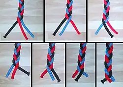
The standard braid is Brunnian: if one removes the black strand, the blue strand is always on top of the red strand, and they are thus not braided around each other; likewise for removing other strands.
A Brunnian braid is a braid that becomes trivial upon removal of any one of its strings. Brunnian braids form a subgroup of the braid group. Brunnian braids over the 2-sphere that are not Brunnian over the 2-disk give rise to non-trivial elements in the homotopy groups of the 2-sphere. For example, the “standard” braid corresponding to the Borromean rings gives rise to the Hopf fibration S3→S2, and iteration of this (as in everyday braiding) is likewise Brunnian.
Real-world examples
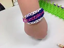
Rainbow loom bracelet showing Brunnian chains
Many disentanglement puzzles and some mechanical puzzles are variants of Brunnian links, with the goal being to free a single piece only partially linked to the rest, thus dismantling the structure.
Brunnian chains are also used to create wearable and decorative items out of elastic bands using devices such as the Rainbow Loom or Wonder Loom.
↑Freedman, Michael H.; Skora, Richard (1987), “Strange actions of groups on spheres”, Journal of Differential Geometry, 25: 75–98, doi:10.4310/jdg/1214440725; see in particular Lemma 3.2, p. 89
This article is adapted from “Brunnian link” on Wikipedia, written by its contributors, and used under CC BY-SA 4.0. Text on this page is available under the same licence. Source snapshot: Wikipedia via Kiwix, 2026-07-20.
In the mathematical field of knot theory, the bridge number, also called the bridge index, is an invariant of a knot defined as the minimal number of bridges required in all the possible bridge representations of a knot.
Definition
Given a knot or link, draw a diagram of the link using the convention that a gap in the line denotes an undercrossing. Call an unbroken arc in this diagram a bridge if it includes at least one overcrossing. Then the bridge number of a knot can be found as the minimum number of bridges required for any diagram of the knot.[1] Bridge numbers were first studied in the 1950s by Horst Schubert.[2] [3]
The bridge number can equivalently be defined geometrically instead of topologically.
In bridge representation, a knot lies entirely in the plane apart for a finite number of bridges whose projections onto the plane are straight lines.
Equivalently, the bridge number is the minimal number of local maxima of the projection of the knot onto a vector, where we minimize over all projections and over all conformations of the knot. In this context, the bridge number is often called the crookedness.
Properties
Every non-trivial knot has bridge number at least two,[1] so the knots that minimize the bridge number (other than the unknot) are the 2-bridge knots.
It can be shown that every n-bridge knot can be decomposed into two trivial n-tangles and hence 2-bridge knots are rational knots.
If K is the connected sum of K1 and K2, then the bridge number of K is one less than the sum of the bridge numbers of K1 and K2.[4]
12Adams, Colin C. (1994), The Knot Book, American Mathematical Society, p.65, ISBN9780821886137.
↑Schultens, Jennifer (2014), Introduction to 3-manifolds, Graduate Studies in Mathematics, vol.151, American Mathematical Society, Providence, RI, p. 129, ISBN978-1-4704-1020-9, MR3203728.
Cromwell, Peter (1994). Knots and Links. Cambridge. ISBN9780521548311.
This article is adapted from “Bridge number” on Wikipedia, written by its contributors, and used under CC BY-SA 4.0. Text on this page is available under the same licence. Source snapshot: Wikipedia via Kiwix, 2026-07-20.
In physical knot theory, each realization of a link or knot has an associated ropelength. Intuitively this is the minimal length of an ideally flexible rope that is needed to tie a given link, or knot. Knots and links that minimize ropelength are called ideal knots and ideal links respectively.
The ropelength problem is open: neither for knots nor for open knots in a long rope has an expression been found (in 2026) that describes the ropelength of tight, ideal knots. The problem is unsolved (as of 2026) for every non-trivial knot.
The ropelength of a knotted curve is defined as the ratio , where is the length of and is the knot thickness of .
Ropelength can be turned into a knot invariant by defining the ropelength of a knot to be the minimum ropelength over all curves that realize .
Ropelength minimizers
One of the earliest knot theory questions was posed in the following terms:
Can I tie a knot on a foot-long rope that is one inch thick?
This asks if there is a knot with ropelength or less. The answer is no: an argument using quadrisecants shows that the ropelength of any nontrivial knot has to be at least .[1] However, the search for the answer has spurred research on both theoretical and computational ground. It has been shown that for each link type there is a ropelength minimizer although it may only be of differentiability class .[2][3] For the simplest nontrivial knot, the trefoil knot, computer simulations have shown that its minimum ropelength is at most 16.372.[1]
Dependence on crossing number
An extensive search has been devoted to showing relations between ropelength and other knot invariants such as the crossing number of a knot. For every knot , the ropelength of is at least proportional to , where denotes the crossing number.[4] There exist knots and links, namely the torus knots and –Hopf links, for which this lower bound is tight. That is, for these knots (in big O notation),[3]
The ropelength of any knot or link must be greater than a universal constant times the three-quarter power of the crossing number, but this constant is not known exactly. This constant is proven to be above 1.1,[4] and torus knots have been tightened with computer simulations that show that this constant must not exceed 10.76.[5]
On the other hand, there also exist knots whose ropelength is larger, proportional to the crossing number itself rather than to a smaller power of it.[6] This is nearly tight, as for every knot,
The proof of this near-linear upper bound uses a divide-and-conquer argument to show that minimum projections of knots can be embedded as planar graphs in the cubic lattice.[7] However, no one has yet observed a knot family with super-linear dependence of length on crossing number and it is conjectured that the tight upper bound should be linear.[8]
Torus knots
Torus knots are known empirically to have the smallest ropelength at a given crossing number.[9] They are also highly symmetric which allows them to be constructed in units of tight non-overlapping configurations which can be extended to arbitrarily large crossing numbers by concatenating the units. A simple example is the double helix which may be concatenated (“stacked together”) to form an alternating torus knot (of which the 31, 51, 71, 91 knots are examples). Olsen and Bohr[10] showed that the most efficient double helix has a contour length of 17 (and two essential crossings), meaning an alternating torus knot would have a ropelength of at most 8.5 per crossing. This number has been reduced through various constructions, the best currently known involves asymmetric double helices and requires 7.32 per crossing.[11] These numbers are measured in radii, and would take half their value if measured in diameters.
It is known that non-alternating knots generally have a lower ropelength than alternating knots with the same crossing number. It has been proven that alternating knots have a ropelength that is at least linear with the crossing number,[12] while non-alternating torus knots can be constructed such that their ropelength is at most a three-quarter power of the crossing number.[13] This implies that at sufficiently large crossing numbers, non-alternating torus knots will have a lower ropelength than alternating torus knots. This is seen empirically even at low crossing numbers, for example the tightest known 10124 knot (a non-alternating torus knot) has a ropelength below 71, while the tightest known 91 has a length of 75.5.[9] Tight constructions of non-alternating T(3Q,Q) torus links will have a ropelength that is less than 19.11C0.75, with the constant typically around 12-13 and bounded below by 5.[14]
Links
Topological links have a ropelength defined similarly to knots. Simple links can be constructed from unknots in such a way that they minimize ropelength. An example is the Hopf link that can be constructed from two circles with perpendicular inclination, each of radius 2, that pass through each others’ centers. The ropelength in this case is 8π. Hopf links can be extended into ropelength minimizing linear chains, in which the interior components are minimized by stadium curves with length 4π+4. More generally, links composed of unknots in which each component has five or fewer components passing through it can be constructed in a way that minimizes ropelength, if each component takes the shape of the minimal convex hull around the cross sections of the curves passing through them.[3] Torus links are subject to similar considerations as torus knots, discussed above.
The ropelength of Borromean rings is conjectured to be 58.006, based on a guitar-shaped construction of parameterized arcs.[9] This tight Borromean configuration is used in the logo of the International Mathematical Union.
References
12Denne, Elizabeth; Diao, Yuanan; Sullivan, John M. (2006), “Quadrisecants give new lower bounds for the ropelength of a knot”, Geometry & Topology, 10: 1–26, arXiv:math/0408026, doi:10.2140/gt.2006.10.1, MR2207788
↑Gonzalez, O.; Maddocks, J. H.; Schuricht, F.; von der Mosel, H. (2002), “Global curvature and self-contact of nonlinearly elastic curves and rods”, Calculus of Variations and Partial Differential Equations, 14 (1): 29–68, doi:10.1007/s005260100089, MR1883599
12Buck, Gregory; Simon, Jonathan (1999), “Thickness and crossing number of knots”, Topology and Its Applications, 91 (3): 245–257, doi:10.1016/S0166-8641(97)00211-3, MR1666650
↑Diao, Y.; Ernst, C.; Thistlethwaite, M. (2003), “The linear growth in the lengths of a family of thick knots”, Journal of Knot Theory and Its Ramifications, 12 (5): 709–715, doi:10.1142/S0218216503002615, MR1999639
↑Diao, Yuanan; Ernst, Claus; Por, Attila; Ziegler, Uta (2019), “The Ropelengths of Knots Are Almost Linear in Terms of Their Crossing Numbers”, Journal of Knot Theory and Its Ramifications, 28 (14): 1950085, doi:10.1142/S0218216519500858
↑Kim; Oh; Huh (2024), “Efficiency of non-identical double helix patterns in minimizing ropelength of torus knots”, Physica Scripta, 99 (7), Bibcode:2024PhyS…99g5240K, doi:10.1088/1402-4896/ad54fd
↑Diao (2024), “The ropelength conjecture of alternating knots”, Mathematical Proceedings of the Cambridge Philosophical Society, 177 (2): 367–369, arXiv:2208.00123, Bibcode:2024MPCPS.177..367D, doi:10.1017/S0305004124000288
↑Cantarella; Kusner; Sullivan (1998), “Tight knot values deviate from linear relations”, Nature, 392 (6673): 237–238, Bibcode:1998Natur.392..237C, doi:10.1038/32558
↑Klotz, A; Thompson, F (2025), Ropelength-minimizing concentric helices and non-alternating torus knots, arXiv:2504.00861
This article is adapted from “Ropelength” on Wikipedia, written by its contributors, and used under CC BY-SA 4.0. Text on this page is available under the same licence. Source snapshot: Wikipedia via Kiwix, 2026-07-20.
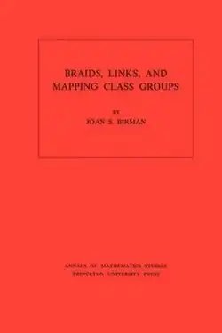
Braids, Links, and Mapping Class Groups is a mathematical monograph on braid groups and their applications in low-dimensional topology. It was written by Joan Birman, and published in 1974 by the Princeton University Press and University of Tokyo Press, as volume 82 of the book series Annals of Mathematics Studies.
Although braid groups had been introduced in 1891 by Adolf Hurwitz and formalized in 1925 by Emil Artin,[1] this was the first book devoted to them.[2] It has been described as a “seminal work”,[3] one that “laid the foundations for several new subfields in topology”.[4]
Topics
Braids, Links, and Mapping Class Groups is organized into five chapters and an appendix. The first introductory chapter defines braid groups, configuration spaces, and the use of configuration spaces to define braid groups on arbitrary two-dimensional manifolds. It provides a solution to the word problem for braids, the question of determining whether two different-looking braid presentations really describe the same group element. It also describes the braid groups as automorphism groups of free groups and of multiply-punctured disks.[5]
The next three chapters present connections of braid groups to three different areas of mathematics. Chapter 2 concerns applications to knot theory, via Alexander’s theorem that every knot or link can be formed by closing off a braid, and provides the first complete proof of the Markov theorem on equivalence of links formed in this way. It also includes material on the conjugacy problem,[5] important in this area because conjugate braids close off to form the same link,[1] and on the “algebraic link problem” (not to be confused with algebraic links) in which one must determine whether two links can be related to each other by finitely many moves of a certain type, equivalent to the homeomorphism of link complements.[2] Chapter 3 concerns representation theory, and includes Fox derivatives and Fox’s free differential calculus,[1] the Magnus representation of free groups and the Gassner and Burau representations of braid groups.[5] Chapter 4 concerns the mapping class groups of 2-manifolds, Dehn twists and the Lickorish twist theorem, and plats, braids closed off in a different way than in Alexander’s theorem.[5]
Chapter 5 is titled “plats and links”.[1] It moves from 2-dimensional topology to 3-dimensional topology, and is more speculative, concerning connections between braid groups, 3-manifolds, and the classification of links. It includes also an analog of Alexander’s theorem for plats, where the number of strands of the resulting plat turns out to be determined by the bridge number of a given link.[5] The appendix provides a list of 34 open problems.[1][5] By the time Wilbur Whitten wrote his review, in June 1975, a handful of these had already been solved.[2]
Audience and reception
This is a book for advanced mathematics students and professionals, who are expected to already be familiar with algebraic topology and presentations of groups by generators and relators. Although it is not a textbook, it could possibly be used for graduate seminars.[1]
Reviewer Lee Neuwirth calls the book “most readable”, “a nice mix of known results on the subject and new material”.[5] Whitten describes it as “thorough, skillfully written” and “a pleasure to read”.[2] Wilhelm Magnus finds it “remarkable” that while covering the subject with full mathematical rigor, Birman has preserved the intuitive appeal of some of its earliest works.[1]
References
1234567Magnus, W. (January 1976), “Review of Braids, Links, and Mapping Class Groups“, Bulletin of the American Mathematical Society, 82 (1): 42–46, doi:10.1090/s0002-9904-1976-13937-7
1234Whitten, Wilbur, “Review of Braids, Links, and Mapping Class Groups“, MathSciNet, MR0375281
The rolling hitch is a knot (see also Magnus hitch) used to attach a rope to a rod, pole, or another rope. A simple friction hitch, it is used for lengthwise pull along an object rather than at right angles. The rolling hitch is designed to resist lengthwise movement for only a single direction of pull.[1]
A common usage while sailing is for rigging a stopper to relax the tension on a sheet so that a jammed winch or block can be cleared.
Naming
Names and reference numbers from ABOK, left to right: “Rolling Hitch (1)” (#1734), “Rolling Hitch (2)” (#1735), “Magnus Hitch” (#1736)
At the turn of the 19th century the knot now known as the “rolling hitch” was called the “Magnus hitch” or “Magner’s hitch”, and the name “rolling hitch” referred to two round turns and two half-hitches.[2] In 1841 Richard Henry Dana Jr. used the present-day names in his work The Seaman’s Friend, and subsequent authors have continued to use this terminology.[1][3]
There are two slightly different hitches commonly known by the name of “rolling hitch”. The Ashley Book of Knots identifies these two variations as “Rolling Hitch (1)” and “Rolling Hitch (2)” and numbers them #1734 and #1735 respectively. Despite the potential for confusion with the older usage, Ashley chose the name “Magnus Hitch” to refer to knot #1736, which is simply #1734 tied with the final hitch made in the opposite direction.[4] Since two distinct variations of the rolling hitch are widely referred to by the same name, and Magnus hitch now may refer to a different knot than it used to, the use of Ashley reference numbers for these related hitches can eliminate ambiguity when required. These hitches are pictured at the right.
When a rolling hitch or Magnus hitch is tied around the standing part of the rope to form an adjustable loop, it is often referred to as a taut-line hitch or one of several other names, although some sources fail to differentiate by using a separate name. Ashley shows this use as #1855, #1856 and #1857.[5]
Tying
Rolling Hitch (1) #1734
This version is preferred when attaching a rope to pole or rod.[4][6] It is effectively a clove hitch with an extra initial turn.
Start with a turn around the object. Bring the working end towards the direction of pull and between the standing part and the object.
Make another wrap around the object, completing a round turn. The wraps of the round turn should progress towards the desired direction of pull. Bring the working end out over the standing part away from the direction of pull.
Complete with a half hitch, moving around the object in the same direction as the first turns, as for a clove hitch.
Dress by snugging the hitch around the object before applying load.
Rolling Hitch (2) #1735
This version is preferred when attaching rope to another rope.[4][6] The first two turns create an awning hitch − a temporary hitch used by riggers when adjusting tent lines.[7] These first two turns are merely a subtle rearrangement in the position of the turns of #1734.
Begin by making a turn around the object, bringing the working end back between the object and the standing part. Cross over the standing part away from the desired direction of pull.
Make a second turn that exactly follows the first, and hence also passes between the object and standing part and then crosses over the standing part, away from the direction of pull. Make sure the second turn “tucks” between the first turn and the standing part; that is what gives this version extra grip when made around another rope.[8]
Finish with a half hitch, moving around the object in the same direction as the first turns, as for a clove hitch.
Dress by snugging the hitch around the object before applying load.
Magnus Hitch #1736
This is tied exactly as #1734, but with the final hitch in the opposite direction. It can be more tricky to snug-up, since both lines emerge from the same side of the hitch, but it has less tendency to twist under load.
Start with a turn around the object. Bring the working end towards the direction of pull and between the standing part and the object.
Make another wrap around the object, completing a round turn. The wraps of the round turn should progress towards the desired direction of pull. Bring the working end out over the standing part away from the direction of pull.
Complete with a half hitch, moving around the object in the opposite direction as the first turns, as for a cow hitch.
Dress by snugging the hitch around the object before applying load.
Security
If the hitch is not made very snug before applying any strain, it will not tighten further under load. When hitching to another rope, Ashley[4] and other sources[8][9] suggest #1735 is more secure. Ashley also states that #1736 has less tendency to twist and marks it “best for the purpose”.[7]
Though effective for moderate loads, the rolling hitch cannot be depended on to hold fast under all conditions. Using stiff and slippery modern fiber ropes, the rolling hitch may be difficult to make hold at all. Friction hitches with additional wraps and more complex structure may provide more security.
The August 2009 edition of Practical Sailor magazine tested various knots used for lengthwise tension applications, and came to the conclusion that when using modern synthetic rope the rolling hitch could not be regarded as secure. They recommended the Icicle hitch as a replacement.[10]
12Clifford W. Ashley, The Ashley Book of Knots (New York: Doubleday, 1944), 292.
↑Lever, Darcy (1998) [1819], The Young Sea Officer’s Sheet Anchor (2nded.), Mineola, NY: Dover Publications, p.8, ISBN978-0-486-40220-8
↑Richard Henry Dana Jr., The Seaman’s Friend: A Treatise on Practical Seamanship, 14th Edition (Boston: Thomas Groom & Co., 1879; Dover Republication 1997), 49.
This article is adapted from “Rolling hitch” on Wikipedia, written by its contributors, and used under CC BY-SA 4.0. Text on this page is available under the same licence. Source snapshot: Wikipedia via Kiwix, 2026-07-20.
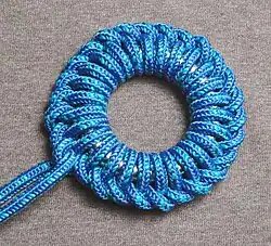
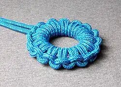
Ringbolt hitching is a series of hitches made around a ring. Covering a ring in hitching can prevent damage if the ring is likely to chafe or strike against something, such as a mooring line or mast.
Continuous
Continuous ring hitching, also known as single ringbolt hitching, is a series of identical hitches made around a ring. This is considered the simplest form of ringbolt hitching.[1]
Alternate ring hitching (ABOK 3604)
Alternate
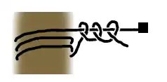
Alternate ring hitching, also known as kackling or keckling, is a type of ringbolt hitching formed with a series of alternate left and right hitches made around a ring.[1]
As a means of dampening sound in row boats when a covert night operation was being undertaken, oar handles were wrapped in keckling knots to prevent wood rubbing on wood.[2]
More Ringbolt hitches
Clifford W. Ashley shows two versions of ABOK 3602. Below is without, above with additional turn.
↑Pope Dudley, Ramage and the Dido (Great Britain: William Collins & Son, 1989), 226. ISBN9780755108275.
This article is adapted from “Ringbolt hitching” on Wikipedia, written by its contributors, and used under CC BY-SA 4.0. Text on this page is available under the same licence. Source snapshot: Wikipedia via Kiwix, 2026-07-20.
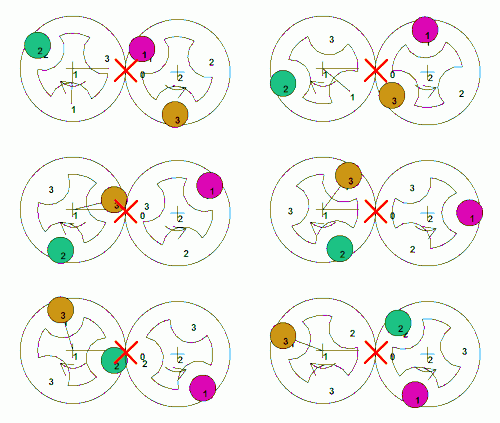
The smallest braiding machine consists of two horn gears and three bobbins. This produces a flat, 3-strand braid.
A braiding machine is a device that interlaces three or more strands of yarn or wire to create a variety of materials, including rope, reinforced hose, covered power cords, and some types of lace.[1][2] Braiding materials include natural and synthetic yarns, metal wires, leather tapes, and others.
Process
Fibers are spun into yarn.
One or more yarns are twisted together to form a strand.
Strands are wound onto bobbins.
Bobbins are mounted on carriers.
Carriers are mounted onto a braiding machine, where the braiding takes place.
Horn gear braider
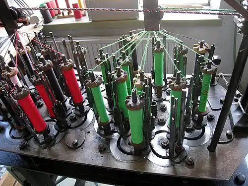
In a horn gear braider, bobbins of thread pass one another to the left and right on pseudo-sinusoidal tracks. The bobbins are mounted on spool carriers that are driven by a series of horn gears. A horn gear is a notched disk driven by a spur gear below on the same shaft; bobbins are transferred between notches of adjacent gears. These gears lie below the track plate that the bobbin carriers ride on. The gears must be driven at multiple points on machines that use two or more bobbin sets and cross-shafts.
On a vertically oriented machine, the braided thread is taken up above the machine. The height and diameter of a guide ring affects the characteristics of the braided product. On horizontal machines, the braiding track plate and associated bobbins are rotated 90 degrees and the braided product is produced parallel to the ground. This enables large stiff braided cables to be output horizontally, which eliminates the need for factory buildings with tall ceilings.
Braiding machines, although they have an apparent complex movement of bobbins, are mechanically simple and robust. Modern versions are reliable and can operate for many hours or even days without attention. This enables factories with hundreds of machines to be operated by just a few workers, which reduces cost of labor and makes products cheaper and/or profits higher. These modern machines have incorporated electronic controls with automated controls. Although ropes, cords and fishing line are still the core products of most braiding companies there are many other products including webbing, cable shielding and automotive products such as reinforced brake lines.
The configuration of horn gears affects the shape of the final braid. A closed circle of gears can be used to make a hollow, circular rope. A single row or horseshoe-configuration can be used to create a flat braid. A grid of gears can be used to create solid-core braids, for example a square braid.
A horn gear braiding machine at the Arbetets Museum (Museum of Work) in Norrköping, Sweden
Horn gears mounted on a track plate
A horn gear machine used to produce a flat braid
A 19th century braider used to produce rickrack. The wavy edges are produced by varying thread tension.[3]
Maypole braider
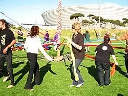
Alternate dancers traveling in opposite directions around a maypole. Notice how dancers use their arms to raise the ribbons to allow other dancers to pass by.
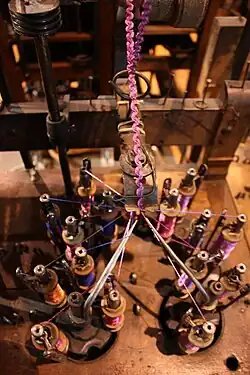
Maypole braiders, also known as circular braiders, are a type of horn gear braider used to produce hollow circular braids. The movement and order of fibers mimics that of ribbons used to decorate a maypole.[4] They were well suited to be driven by the steam engines of the industrial revolution and electric motor-powered machines were common by the beginning of the 20th century.
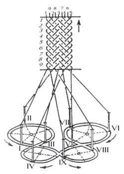
Common types of braiding machines work in much the same way as the process of decorating a maypole. At the start of decorating a maypole, an even number of ribbons are tied to the top of the pole. Each ribbon is held by one person, and the group of people form a ring about the base of the pole. Half the people travel clockwise and the other half counter clockwise. When passing people traveling in the opposite direction, individuals alternate passing to the right and to the left. This results in a downward forming braid on the pole. As the braid works its way down the pole, the ribbons become shorter and the angle of forming changes as the braid works lower on the pole. On a standard braiding machine, the supply lines are a constant angle and at a constant tension and hence the output braided product is uniform.
This type of braiding can be used to braid a sheathe over a cable as it is drawn through the middle of the machine and is used to produce shielded electrical cables and fibre reinforced hoses. This type of machine is also used to weave fibres such as carbon fibres onto a hollow substrate to produce high performance composite parts, being used in producing rigid lightweight components such as bike frames and yacht masts.
Square braider
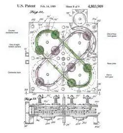
1989 US patent for a horn gear braider specifically designed to create a square braid from eight strands of yarn.[5]
A square braider uses a grid of gears and intersecting tracks to produce a solid-core braid.
In the patent image on the right, the braider has two tracks, one shaded in green and one shaded in red. Four bobbin carriers slide along each track. The four carriers shaded in green travel around the green track in the counter-clockwise direction, and the four carriers shaded in red travel around the red track in the clockwise direction. As the two tracks cross over, the strands twist around each other, making a braid.
The carriers are pushed by four horn gears in the base plate. Each of the horn gears has a gear and a horn on a common shaft. The gears intermesh with each other, with alternate gears traveling in opposite directions. Each horn has four slots for pushing a bobbin carrier. The bobbin carriers get passed along from one horn to the next as they make their way along a track.
Wardwell Rapid Braider
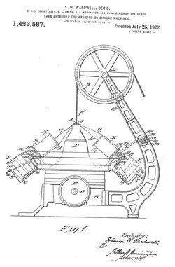
Patent for Wardwell Rapid Braider
The speed of a horn gear braider is limited by the effort needed to force bobbin carriers to follow a serpentine path. In 1922, Simon W. Wardwell solved this problem by moving the strands of yarn instead of the carriers, allowing the carriers to follow a simple circular path.[6] The carriers are in two counter-rotating rings, while lever arms driven by a cam guide the strands of yarn from the outer ring up and down between the carriers of the inner ring. Because a lever arm has much less mass than a bobbin and carrier, the machine can run faster.
Track and column braider
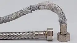
Braiding gives a metal hose like this flexibility and strength.
In a track and column braider, bobbin carriers follow tracks in a two dimensional array of rows and columns, instead of circular paths defined by horn gears.[7]
↑Adanur, S. (1995). “Braiding and Narrow Fabrics”. Wellington Sears Handbook of Industrial Textiles. Technomic Publishing Company, Inc. pp.133–138. ISBN1566763401.
↑USpatent 4803909,Michael F. Smith,“Apparatus and method for automated braiding of square rope and rope product produced thereby”,issued February 14, 1989
↑USpatent 1423587,Simon W. Wardwell,“Yarn retriever for braiding or similar machines”,issued July 25, 1992
↑Soares, Carlos (1999). Soares, Carlos A. Mota; Soares, Cristóvão M. Mota; Freitas, Manuel J. M. (eds.). Mechanics of composite materials and structures. Dordrecht Boston, MA: Kluwer Academic Publishers. doi:10.1007/978-94-011-4489-6. ISBN9780792358701.
Bibliography
Potluri, P.; Nawaz, S. (2011). “Developments in Braided Fabric”. In Gong, R. H. (ed.). Specialist Yarn and Fabric Structures: Developments and Applications. Woodhead Pub. pp.333–354. ISBN978-0857093936.
External links
YMCORP (September 26, 2011). “Cam Ring Wardwell Slow Speed”. YouTube. Archived from the original on 2021-12-21. Retrieved February 25, 2016.: YouTube video of a Wardell braider, with a yellow-painted cam
This article is adapted from “Braiding machine” on Wikipedia, written by its contributors, and used under CC BY-SA 4.0. Text on this page is available under the same licence. Source snapshot: Wikipedia via Kiwix, 2026-07-20.
In mathematics, a commutativity constraint on a monoidal category is a choice of isomorphism for each pair of objects A and B which form a natural family. In particular, to have a commutativity constraint, one must have for all pairs of objects .
A braided monoidal category is a monoidal category equipped with a braiding—that is, a commutativity constraint that satisfies axioms including the hexagon identities defined below. The term braided references the fact that the braid group plays an important role in the theory of braided monoidal categories. Partly for this reason, braided monoidal categories and other topics are related in the theory of knot invariants.
Alternatively, a braided monoidal category can be seen as a tricategory with one 0-cell and one 1-cell.
Braided monoidal categories were introduced by André Joyal and Ross Street in a 1986 preprint.[1] A modified version of this paper was published in 1993.[2]
The hexagon identities
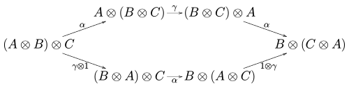
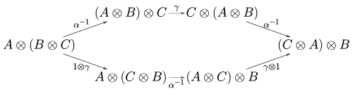
For along with the commutativity constraint to be called a braided monoidal category, the following hexagonal diagrams must commute for all objects . Here is the associativity isomorphism coming from the monoidal structure on :
,
Properties
Coherence
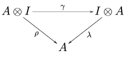
It can be shown that the natural isomorphism along with the maps coming from the monoidal structure on the category , satisfy various coherence conditions, which state that various compositions of structure maps are equal. In particular:
The braiding commutes with the units. That is, the following diagram commutes:
The action of on an -fold tensor product factors through the braid group. In particular,
as maps . Here we have left out the associator maps.
Variations
There are several variants of braided monoidal categories that are used in various contexts. See, for example, the expository paper of Savage (2009) for an explanation of symmetric and coboundary monoidal categories, and the book by Chari and Pressley (1995) for ribbon categories.
Symmetric monoidal categories
A braided monoidal category is called symmetric if also satisfies for all pairs of objects and . In this case the action of on an -fold tensor product factors through the symmetric group.
Ribbon categories
A braided monoidal category is a ribbon category if it is rigid, and it may preserve quantum trace and co-quantum trace. Ribbon categories are particularly useful in constructing knot invariants.
Coboundary monoidal categories
A coboundary or “cactus” monoidal category is a monoidal category together with a family of natural isomorphisms with the following properties:
for all pairs of objects and .
The first property shows us that , thus allowing us to omit the analog to the second defining diagram of a braided monoidal category and ignore the associator maps as implied.
Examples
The category of representations of a group (or a Lie algebra) is a symmetric monoidal category where .
The category of representations of a quantized universal enveloping algebra is a braided monoidal category, where is constructed using the universal R-matrix. In fact, this example is a ribbon category as well.
↑André Joyal; Ross Street (1993), “Braided tensor categories”, Advances in Mathematics, 102: 20–78, doi:10.1006/aima.1993.1055
Chari, Vyjayanthi; Pressley, Andrew. “A guide to quantum groups”. Cambridge University Press. 1995.
Savage, Alistair. Braided and coboundary monoidal categories. Algebras, representations and applications, 229–251, Contemp. Math., 483, Amer. Math. Soc., Providence, RI, 2009. Available on the arXiv
This article is adapted from “Braided monoidal category” on Wikipedia, written by its contributors, and used under CC BY-SA 4.0. Text on this page is available under the same licence. Source snapshot: Wikipedia via Kiwix, 2026-07-20.